Lid-driven cavity case with OpenFOAM2D and KratosStructure2D
This case is an FSI-adaptation of the famous lid-driven cavity case, calculated using OpenFOAM and KratosMultiphysics StructuralMechanicsApplication. For more information with respect to this case refer to this example.
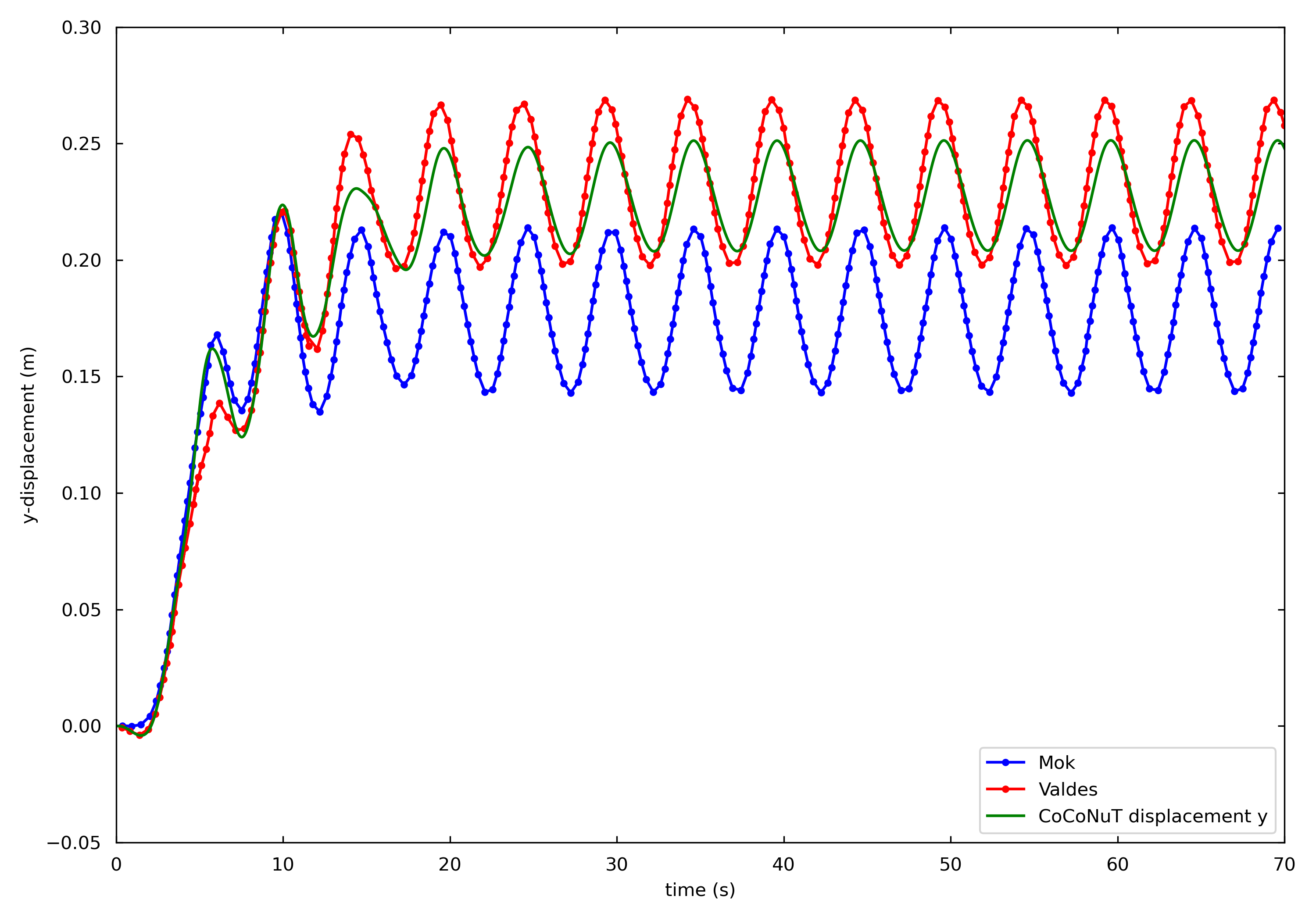
Reference solutions are available from Mok [1] and Valdes [2]. The figure belows shows a comparison with the solution of the examples with Fluent and OpenFOAM.

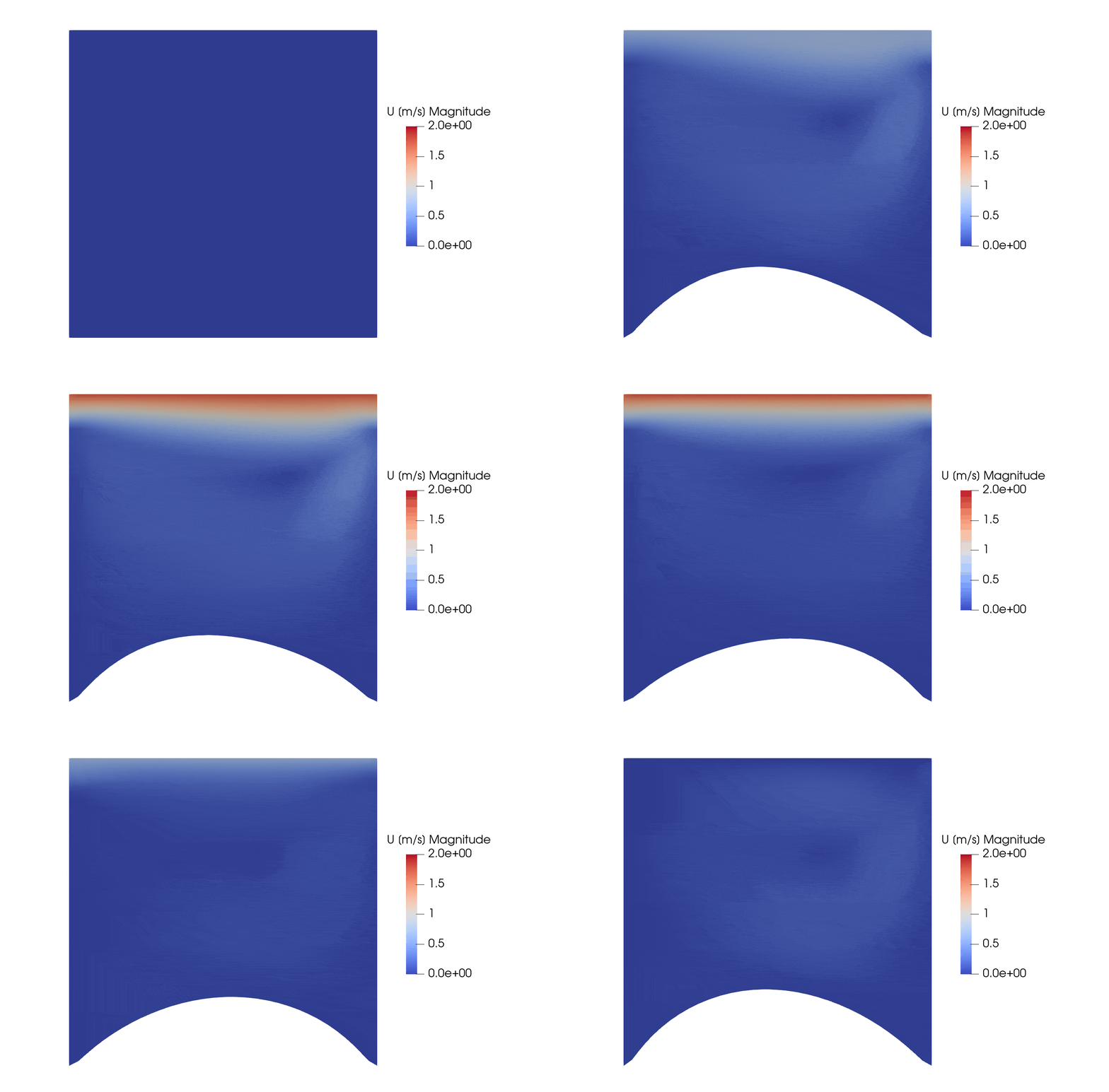
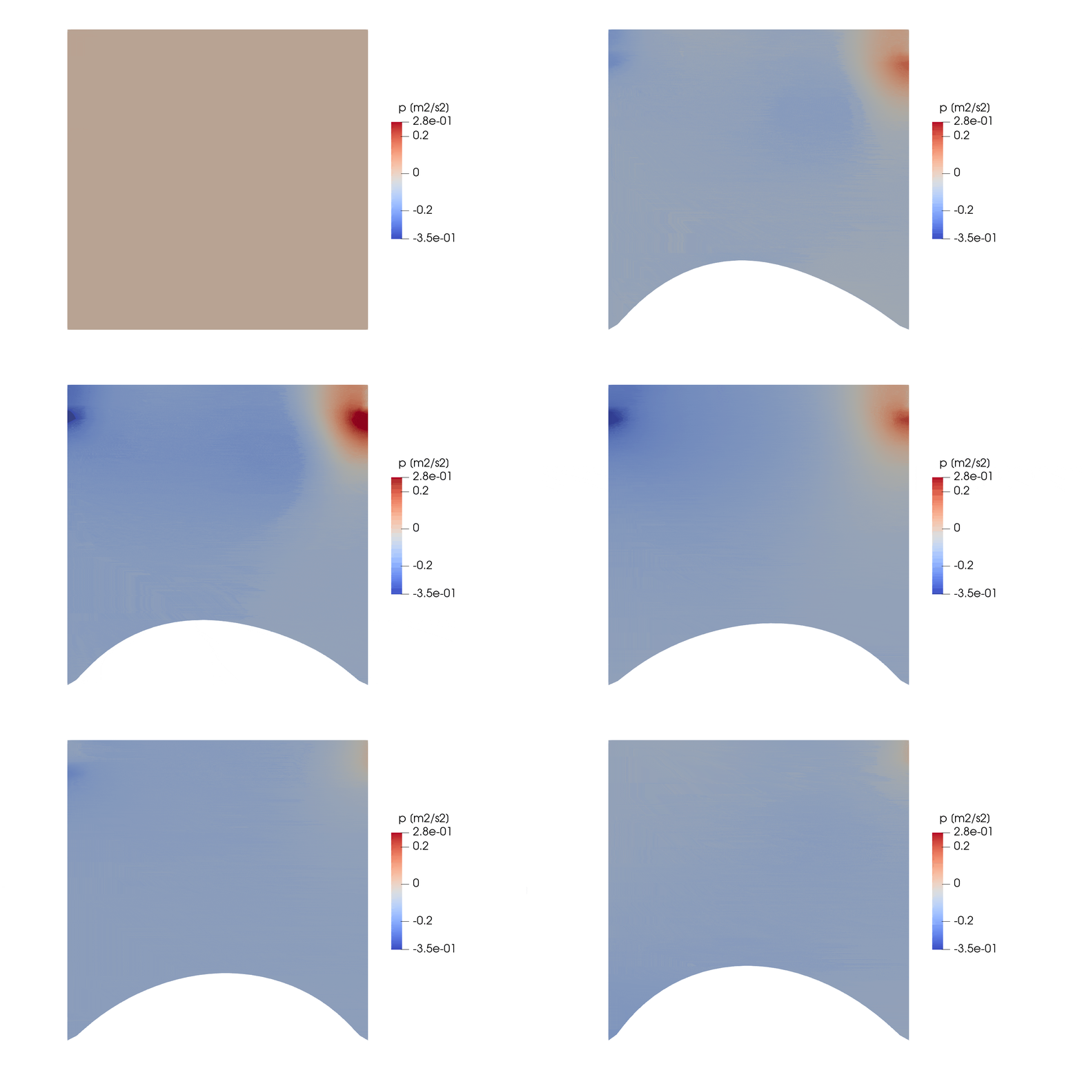
The following figures show contour plots of the pressure and velocity for this example (with Paraview).


Coupling algorithm
The coupling technique used is the interface quasi-Newton algorithm with an approximation for the inverse of the Jacobian from a least-squares model (IQN-ILS).
No reuse is employed, so the reuse parameter q is set to 0.
Predictor
The initial guess in every time step is done using the linear predictor.
Convergence criterion
Two convergence criteria have been specified:
- The number of iterations in every time step is larger than 10.
- The residual norm of the displacement is smaller than 10^{-9}.
When either criterion is satisfied the simulation stops.
Solvers
The flow solver is the OpenFOAM solver pimpleFOAM. A quadrilateral mesh is used with 32 cells on each side of the cavity, made with blockMesh.
The structural solver is KratosMultiphysics StructuralMechanicsApplication (abbreviated KratosStructure). The deformable bottom is meshed with 2 layers of 32 TotalLagrangianElement2D4N elements. The movement of the left and right side is constrained.
To exchange information between the solvers on the fluid-structure interface, the use of mappers is required. Because a two-dimensional calculation in OpenFOAM has one cell in the depth direction, the coordinates of the nodes are actually three-dimensional. Therefore, the displacement serving as input to the flow solver is first mapped using the mapper MapperDepth2DTo3D and subsequently mapped using a radial basis mapper. The resulting pressure and traction forces are located on the face centers, which all lie in the same plane as where the forces are applied in the structural solver. This means no additional transformer is required and only a radial basis mapper has to be applied. Mapping the flow solver instead of the structural solver, means that the coupled solver will work with the interface containing the displacements stored in Kratos nodes and not the interface which has stored the displacements in twice as many OpenFOAM nodes.
References
[1] Mok D. P., “Partitionierte Lösungsansätze in der Strukturdynamik und der Fluid−Struktur−Interaktion”, PhD thesis: Institut für Baustatik, Universität Stuttgart, 2001.
[2] Valdés G. and Gerardo J., “Nonlinear Analysis of Orthotropic Membrane and Shell Structures Including Fluid-Structure Interaction”, PhD thesis: Universitat Politècnica de Catalunya, 2007.